
Today we are going to take a look at creating your own Esphome alarm board
Introduction
I previously Did a video of a premade board you can buy on AliExpress here:
we have also coved how to add more GPIO pins to your esp32 in this video, article here Today we will continue working on the DIY alarm board.
Why Do this?
Why not just Buy an premade professional looking board?
- Price excluding the time spent building it is a lot cheaper than buying a premade board
- The parts used is commonly available even locally is most countries
- The ability to replace a single broken component instead of the entire board easily by plugging in a replacement.
- Its Fun and a good starting point to try and expand your knowledge.
Requirements
- Esp32 development board
- 2 x pcf8575 I/O expander
- 1x Relay
- 15X9 prototype PCB/Perfboard
- Pin Headers you can get a few of the long ones and cut then to size
- PCB Screw Terminal Block I have a mix of 3 and 2 pin normally get these in bulk.
- Buck Converter I Used a mini I would recommend the standard that is more reliable.
- Wire I used striped cat5/6 cable that was laying around
- Multimeter
- Optional 433mhz receiver you need a antenna as well (these are cheap and some of them does not preform that well that is why this is optional as you may already have something like a sonoff bridge or similar)
The Layout
This is something that you would need to work out before soldering the pin headers.
I placed mine specifically in a row because of the inputs on the modules we are using. If you are using isolated wires you may have a bit more freedom on your placements because you can cross wires. In my case I had unshielded wires and had to make sure they are not touching unless its a ground wire, those are all connected.
Below is a Photo of how mine was placed on the board as well as a diagram showing how the wires were connected.
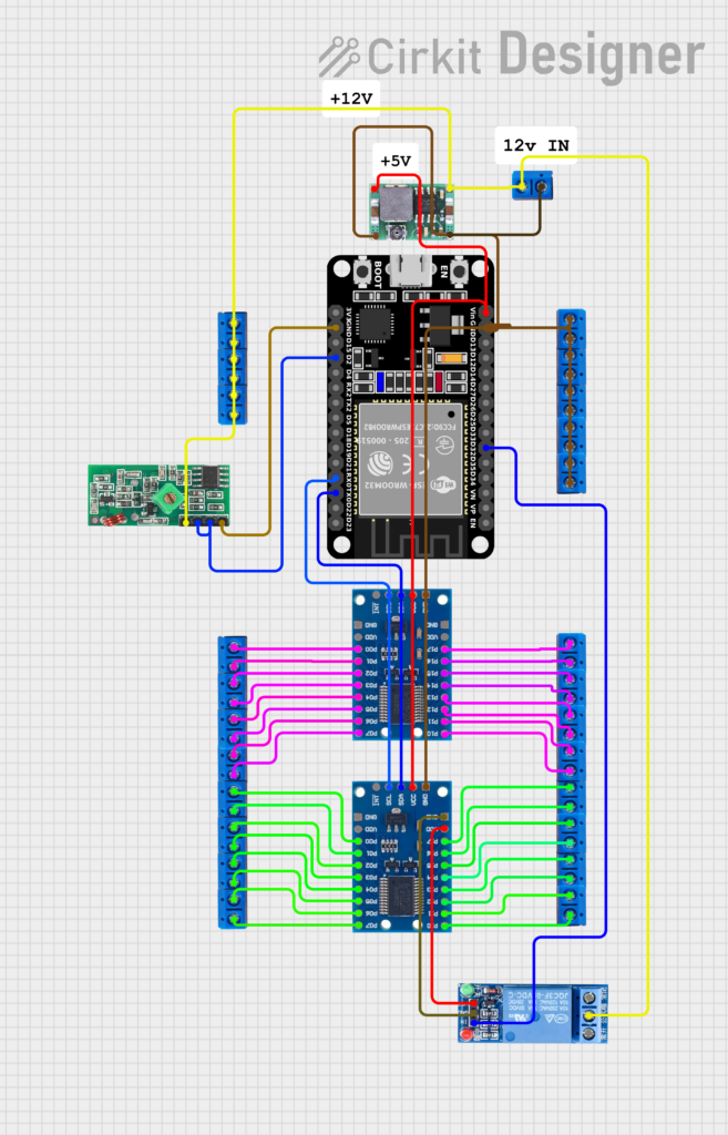
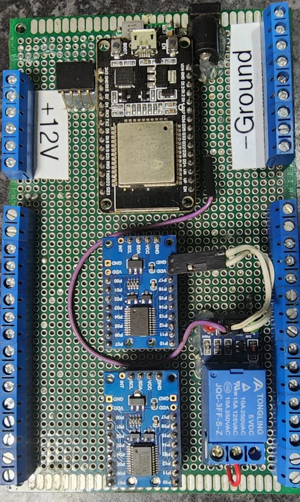
The relay was added at the end using a isolated 12v positive line this will be used to power the siren once connected. and on the top I used jumpers to pull power and Ground from one of the pcf8575 I/O expander modules. I also added a jumper on the top side of the board from the Relay to the data pin of the esp. if you plan for this before you may be able to add headers for this too.
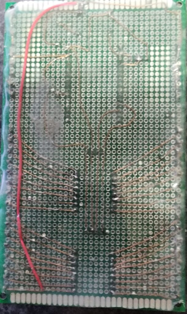
Unfortunately the this is the best photos I can take of this thing the back side is even harder because I completely sealed it with hot glue to avoid a short.
Once you have your layout ready its time to put on some music or a tv show and and start soldering the headers onto the board best tip I have for this is to plug each module into the headers and then insert it to the perfboard for soldering.
There are plenty of YouTubers that explain how to do this properly and I am not one of them this was my first attempt at doing something like this and why I used a bigger board and the specific layout. I would recommend you take a look at some videos if you need a few tips.
After you have everything soldered together DO NOT POWER ON THE BOARD.
With all the modules unplugged use a multimeter to test all the connections including a continuity test between Positive and ground to make sure nothing is sorting this is an extremely important step.
After you have tested and confirmed everything is in order you can connect Only the Buck converter to 12v power on the input is shown on them like in picture below.
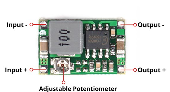
You need to connect your 12v power supply to the input and then the multimeter to the output you may need 4 hands or some clips that connect the outputs to the multimeter.
once you get the reading for the output voltage on the multimeter you need to start turning the Adjustable Potentiometer, These things are horrible to adjust and be gentle they also break easily while adjusting them.
While turning the potentiometer look at the multimeter and try to bring the voltage down or up depending on the turning direction to get to around 5v DO NOT GO OVER 5V mine is currently at 4.7V and everything seems to be working fine if its too low you may have issues triggering relays, too high then magic smoke.
Pcf8575 I/O expander Configuration
The last Step Before plugging everything into your board is a bit more solder work on the expander boards as we need to give them each a different address to work over i2c.
If you want more info on this I have another video covering this briefly and how to have esphome show the addresses that is connected to i2c here.
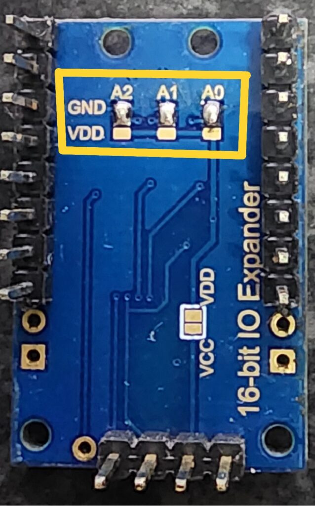
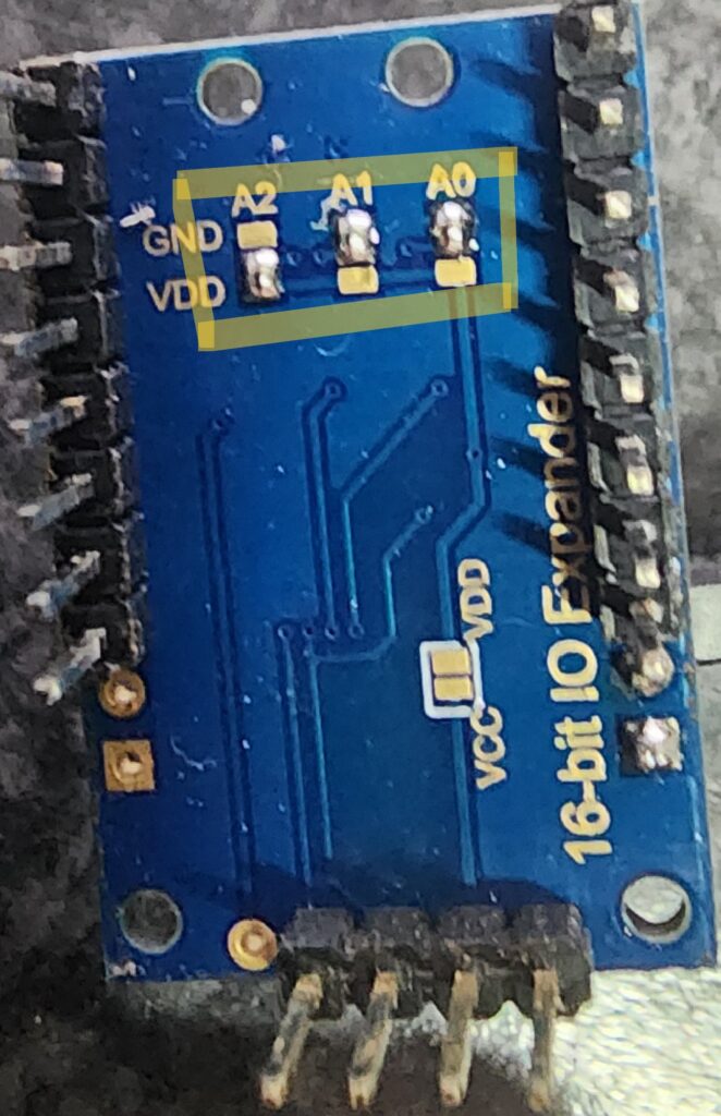
On the Back side of the expander bords you need to bridge a few tabs to get different addresses see pictures below of how both of mine has been connected, It does not need to be the same but the code I am providing uses these specific addresses, You can change this of course.
The placement location of the expanders on the pcb, if its the first or last one in the row would not effect the addresses
Flashing the esp32
At this point I would recommend flashing the esp32 with ESPhome before plugging in the modules to the board. Do not have the usb and 12v power connected at the same time. So Flash the eso not connected to the board now. Then you can add the code remotely once you have confirmed that you can access the board in esphome/homeassistant.
If you are new here is a Getting started guide/video for ESPhome.
Finally Putting it together
Now its time to plug in all the modules make sure you plug in the Esp32 the right way around the rest of the modules should be able to go in only one way unless you also added a removable Buck converter Confirm the orientation of this as well.
Power on the board using the 12v power and everything should now be connected and working.Side note if you injure yourself, others or damage your components, burn down your house/City/world. I do not take any responsibility. This website is me documenting what I did to get to the desired results I needed and I cannot be held responsible for the actions of others. Do This at your own risk.
Flashing updated code
If you had no magic smoke after everything is connected and the esp32 is powered on Check to confirm if the device is online in ESPHome.
If it is not then you may have had a short somewhere and you would need to check your connections or confirm that it is connected correctly. Also test the esp again unplugged from the board connected to the usb to confirm that it is still functioning.
Code
There are some basic notes in the code you can place this under your Wi-Fi config in ESPHome.
captive_portal:

web_server:
  port: 80


# remote_receiver:      # Enable this if you are using a 433mhz Receiver
#   pin: GPIO2
#   dump:
#   - rc_switch
#   tolerance: 60%
#   filter: 250us
#   idle: 2ms
#   buffer_size: 2kb

i2c:

  sda: GPIO1        # TX0 Pin of ESP
  scl: GPIO3        # RX0 Pin of ESP
  scan: true
  id: bus_a         # Just a name for the i2c "network" if you change this you also need to match the name where we use it in the rest of the code.

pcf8574:
  - id: 'pcf8575_hub'       # This is the name of One of the expansion boards you can change it but you will also need to change it on all of the sensors as it need to know what device its connected to
    address: 0x20
    i2c_id: bus_a           # Reference to the specific bus/i2c "network"
    pcf8575: true

  - id: 'pcf8575_hub2'      # This is the name of the Second expansion boards you can change it but you will also need to change it on all of the sensors as it need to know what device its connected to
    address: 0x24
    i2c_id: bus_a
    pcf8575: true


switch:
  - platform: gpio
    pin: 32
    inverted: true
    id: Siren_relay                # For ESPHome to be able to reference the relay can also be used in Auotomations in Esphome.
    name: "Siren"
    icon: "mdi:BullhornOutline"    # Icon shown in Home Assistant you can get a list of Icons here https://pictogrammers.com/library/mdi/


binary_sensor:                      # This code is setup to use all the pins as input Binary sensors If you want to use them as outputs trigger a relay of something you can move the sensor under the switch option and chage mode: INPUT to mode: OUTPUT
  - platform: gpio                  # These are all the same the only difference would be the Pin number and the ID of the expansion board
    name: "pin0"                    # <<<< This is the name of the entity in Home Assistant you can Change these to whatever is connected to the pin you can also update the ID if needed.
    id: pin0
    device_class: door              # This is used to tell Home assistant what type of sensor this is for example Door,Window,Motion. This is also important for AlarmO to be able to see the sensors. see full list here https://developers.home-assistant.io/docs/core/entity/binary-sensor/#available-device-classes
    pin:
      pcf8574: pcf8575_hub
      number: 0
      mode: INPUT                   # Changing this to OUTPUT and placing under the Switch will allow relay control on this pin
      inverted: true

  - platform: gpio
    name: "pin1"
    id: pin1
    device_class: window
    pin:
      pcf8574: pcf8575_hub
      number: 1
      mode: INPUT
      inverted: true

  - platform: gpio
    name: "pin2"
    id: pin2
    device_class: motion
    pin:
      pcf8574: pcf8575_hub
      number: 2
      mode: INPUT
      inverted: false       #For my PIR sensors used I did not need to invert the states or else the statuses are inverted as well.

  - platform: gpio
    name: "pin3"
    id: pin3
    device_class: door
    pin:
      pcf8574: pcf8575_hub
      number: 3
      mode: INPUT
      inverted: true

  - platform: gpio
    name: "pin4"
    id: pin4
    device_class: door
    pin:
      pcf8574: pcf8575_hub
      number: 4
      mode: INPUT
      inverted: true

  - platform: gpio
    name: "pin5"
    id: pin5
    device_class: door
    pin:
      pcf8574: pcf8575_hub
      number: 5
      mode: INPUT
      inverted: true

  - platform: gpio
    name: "pin6"
    id: pin6
    device_class: door
    pin:
      pcf8574: pcf8575_hub
      number: 6
      mode: INPUT
      inverted: true

  - platform: gpio
    name: "pin7"
    id: pin7
    device_class: window
    pin:
      pcf8574: pcf8575_hub
      number: 7
      mode: INPUT
      inverted: true

  - platform: gpio
    name: "pin8"
    id: pin8
    device_class: window
    pin:
      pcf8574: pcf8575_hub
      number: 8
      mode: INPUT
      inverted: true

  - platform: gpio
    name: "pin9"
    id: pin9
    device_class: window
    pin:
      pcf8574: pcf8575_hub
      number: 9
      mode: INPUT
      inverted: true

  - platform: gpio
    name: "pin10"
    id: pin10
    device_class: window
    pin:
      pcf8574: pcf8575_hub
      number: 10
      mode: INPUT
      inverted: true

  - platform: gpio
    name: "pin11"
    id: pin11
    device_class: window
    pin:
      pcf8574: pcf8575_hub
      number: 11
      mode: INPUT
      inverted: true

  - platform: gpio
    name: "pin12"
    id: pin12
    device_class: window
    pin:
      pcf8574: pcf8575_hub
      number: 12
      mode: INPUT
      inverted: true

  - platform: gpio
    name: "pin13"
    id: pin13
    device_class: window
    pin:
      pcf8574: pcf8575_hub
      number: 13
      mode: INPUT
      inverted: true

  - platform: gpio
    name: "pin14"
    id: pin14
    device_class: window
    pin:
      pcf8574: pcf8575_hub
      number: 14
      mode: INPUT
      inverted: true

  - platform: gpio
    name: "pin15"
    id: pin15
    device_class: window
    pin:
      pcf8574: pcf8575_hub
      number: 15
      mode: INPUT
      inverted: true


  - platform: gpio                      # start of second expander same notes apply as above
    name: "2pin0"
    id: pin17
    device_class: window
    pin:
      pcf8574: pcf8575_hub2
      number: 0
      mode: INPUT
      inverted: True

  - platform: gpio
    name: "2pin1"
    id: pin18
    device_class: window
    pin:
      pcf8574: pcf8575_hub2
      number: 1
      mode: INPUT
      inverted: True

  - platform: gpio
    name: "2pin2"
    id: pin19
    device_class: window
    pin:
      pcf8574: pcf8575_hub2
      number: 2
      mode: INPUT
      inverted: True

  - platform: gpio
    name: "2pin3"
    id: pin20
    device_class: window
    pin:
      pcf8574: pcf8575_hub2
      number: 3
      mode: INPUT
      inverted: True

  - platform: gpio
    name: "2pin4"
    id: pin21
    device_class: window
    pin:
      pcf8574: pcf8575_hub2
      number: 4
      mode: INPUT
      inverted: True


  - platform: gpio
    name: "2pin5"
    id: pin22
    device_class: window
    pin:
      pcf8574: pcf8575_hub2
      number: 5
      mode: INPUT
      inverted: True

  - platform: gpio
    name: "2pin6"
    id: pin23
    device_class: window
    pin:
      pcf8574: pcf8575_hub2
      number: 6
      mode: INPUT
      inverted: True

  - platform: gpio
    name: "2pin7"
    id: pin24
    device_class: window
    pin:
      pcf8574: pcf8575_hub2
      number: 7
      mode: INPUT
      inverted: True

  - platform: gpio
    name: "2pin8"
    id: pin25
    device_class: motion
    pin:
      pcf8574: pcf8575_hub2
      number: 8
      mode: INPUT
      inverted: false


  - platform: gpio
    name: "2pin9"
    id: pin26
    device_class: motion
    pin:
      pcf8574: pcf8575_hub2
      number: 9
      mode: INPUT
      inverted: false

  - platform: gpio
    name: "2pin10"
    id: pin27
    device_class: motion
    pin:
      pcf8574: pcf8575_hub2
      number: 10
      mode: INPUT
      inverted: false

  - platform: gpio
    name: "2pin11"
    id: pin28
    device_class: motion
    pin:
      pcf8574: pcf8575_hub2
      number: 11
      mode: INPUT
      inverted: false

  - platform: gpio
    name: "2pin12"
    id: pin29
    device_class: motion
    pin:
      pcf8574: pcf8575_hub2
      number: 12
      mode: INPUT
      inverted: false

  - platform: gpio
    name: "2pin13"
    id: pin30
    device_class: motion
    pin:
      pcf8574: pcf8575_hub2
      number: 13
      mode: INPUT
      inverted: false

  - platform: gpio
    name: "2pin14"
    id: pin31
    device_class: motion
    pin:
      pcf8574: pcf8575_hub2
      number: 14
      mode: INPUT
      inverted: false

  - platform: gpio
    name: "2pin15"
    id: pin32
    device_class: motion
    pin:
      pcf8574: pcf8575_hub2
      number: 15
      mode: INPUT
      inverted: false
Testing
Once you have uploaded the code before editing it I would recommend testing all the pins by using a jumper cable from ground while using the log file to see if the state changes on all the sensor pins you can also test the relay by visiting the webpage created on the esp32.
If you notice a Pin not working you would need to check the connection on the board and confirm your soldering.
Conclusion
Yes this is a lot of work to first setup then comparing to the premade available boards but, once built you can easily replace any component without needing to replace an entire board or SMD Work.
This is cheap to build and components are available locally in most countries.
You can use this on 5v PIR sensors and also use the pins as outputs to trigger relays if needed.
For the ones still reading if you know how to make a PCB or know someone who is able to make one for free to the community. The only thing we need on it would be the holes for pin headers and Screw Terminal Blocks with the right spacing to save a lot of time soldering small wires. Everything needs to be replaceable on it is main goal.
This would be a free file provided for anyone that is interested in using it.
You can contact me at [email protected]

